May 23, 2011
4 min. read
The AVR ISP II is a device to program an AVR microcontroller using a 6 pin header in a circuit. It does not contain any capability to power the circuit being programmed. This could be very handy.
Dave Jones at the EEVBlog has a video about adding power to the ISP cable, using an LM317 to provide both 5V and 3.3V. The issue with this, as he stated, was that the 5V source was very close to the required dropout voltage of the regulator to get the 3.3V. In addition, resistors are needed to set the voltage. This is my version of hacking on the AVR ISP II.
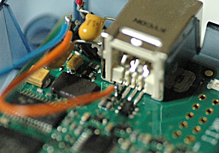
I decided to use a Low Drop Out regulator for 3.3V. The specific part I used was the BD33KA5 in a TO252-3 package (pdf). I started by soldering the tab of the LDO 3.3V regulator to the shield ground on the USB jack. My new $50 Atten 858D+ hot air rework station made this much easier than an iron. I had tried and failed with the iron before the 858D+ arrived. According to the data sheet, I needed a 1uF on both Vcc and 3.3V output pins. I used some tantalums that I had around.
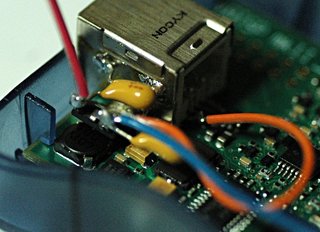
I soldered the Vcc side of the regulator directly to the USB 5V pin and also soldered a 5V wire from the regulator back to the switch.
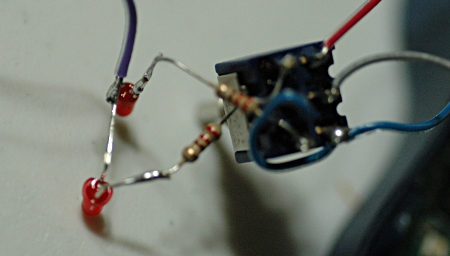
I decided that I would use a DPDT ON-OFF-ON switch to allow for 5V - 0V - 3.3V output options. I used a double pole, instead of a single pole, so I could use the other pole of the switch to power little LEDs beside the 5V and 3.3V labels. This will give an indication to make it harder to accidentally power into a live circuit. I decided to mess with surface mount LEDs. This would turn out to be a mistake.
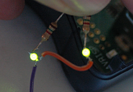
When I got the LEDs from DigiKey, they were tiny. Like, stick to your soldering iron when trying to solder tiny. Like, Joe you are going to snap them in half a couple times. I soldered the LED to a 1/4W resistor and a wire. This allowed me to test the power. For 2mA, these were pretty decent. I snapped one LED during this, but resoldered on another one.
After messing around with soldering those to the switch and trying to bend the resistors into place, I snapped both of them. I think it might have been possible with thin wire and would have looked good. But I was done with this SMD stuff for now. :)
I grabbed some 3mm red LEDs that I have had since I was in middle school. These let me also fix the one problem I didn’t think about. My SMD LEDs were crossed, so the light would be illuminated the opposite direction of the switch toggle. I crossed the hookup for the 3mm LEDs. I had to change the current limiting resistors from 1.5k to 220. I figured about 16 mA for these LEDs and it turned out about right. (I am running the LEDs directly from the 5V power.)
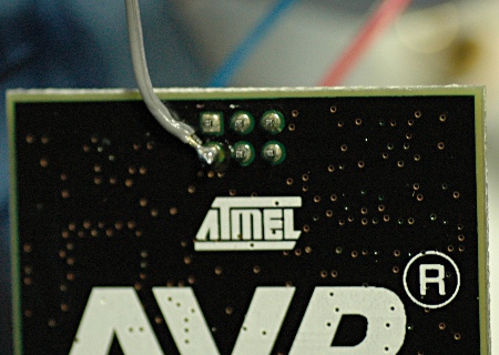
With 5V and 3.3V soldered to each side of one pole, I wired the center down to pin 2 of the ISP header. Now we can power it with 5V, 3.3V or Nothing.
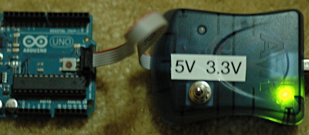
I connected the AVR ISP II to the ISP connector on an Arduino Uno board. With no power, the ISP should work as normal, if you power the Uno board.
I then tried the 5V power to the Uno board and that looked good.
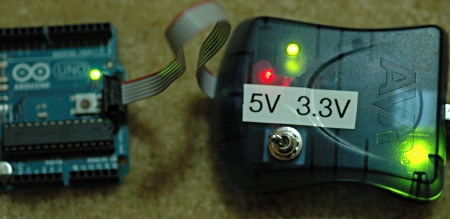
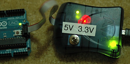
Finally I thought the Uno might run on 3.3V, even though I don’t think you are supposed to use up to 16 MHz with 3.3V. I didn’t try programming, but the power definitely works.
I’m not terribly pleased with the results of hot gluing the LEDs. It spreads the light too much. If I was to do it again, I wouldn’t try to cover around the LED, I would have put a dab of hot glue and stuck the LED into the glue. I did find out that the 858D+ rework air iron was again helpful to fix my glue mess. By setting the temperature down to the minimum of 100 C, I was able to remelt the glue and push the LEDs in deeper with a flat screw driver, without hurting the plastic case at all.
Anyhow, it is a test device, so it doesn’t have to look good. It just has to work. Work it does.